Autonomous Electric Car Competition
Vision Algorithms and Communication Systems of BURST Autonomous Vehicles
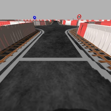
The RoboTaksi project requires the students to complete a predefined track. Two important aspects of this project were the vision algorithms and control of the car:
YOLOv3 Model in Simulation
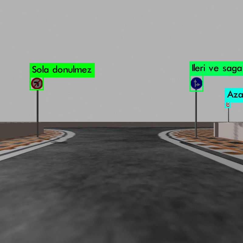
For the object detection, YOLOv3, a CNN model was used. It basically divides the image into a grid and predicts bounding boxes and class probabilities for each grid cell simultaneously. The images to train the model were obtained from the simulation as well as the real-life datasets.

Traffic Sign Position Detection
To pinpoint traffic sign positions,The position of the markers is approximated based on the assumption that the height of the markers is constant and the incline of the track is negligible. With these assumptions, the determination of the markers’ position in a three-dimensional coordinate system, where the vehicle’s direction is considered as the x-axis and the left direction as the y-axis, is calculated as follows:
The angle of the marker relative to the camera’s field of view is calculated by:
\[s = \frac{\text{FOV}_x \left( \frac{P_x}{2} - \text{sp}_x \right)}{P_x} \text{ rad}\]The x-coordinate of the marker’s position in the vehicle’s system is calculated by:
\[s_x = \frac{P_y}{2} \left( \frac{P_y}{2} - \text{sp}_y \right) \times \left( h_{\text{marker}} - h_{\text{camera}} \right) \tan\left( \frac{\text{FOV}_y}{2} \right)\]The y-coordinate of the marker’s position in the vehicle’s system is calculated by:
\[s_y = s_x \tan(s)\]Here, s represents the marker’s relative angle, and s_x, s_y represent the marker’s relative position in the vehicle’s system. The camera-specific characteristics are defined as FOV_x,y = 1.39 rad, P_x,y = 800 pixels.
Lane Recognition Techniques
We explored various techniques for lane recognition:
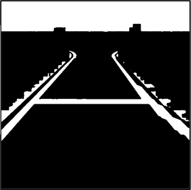
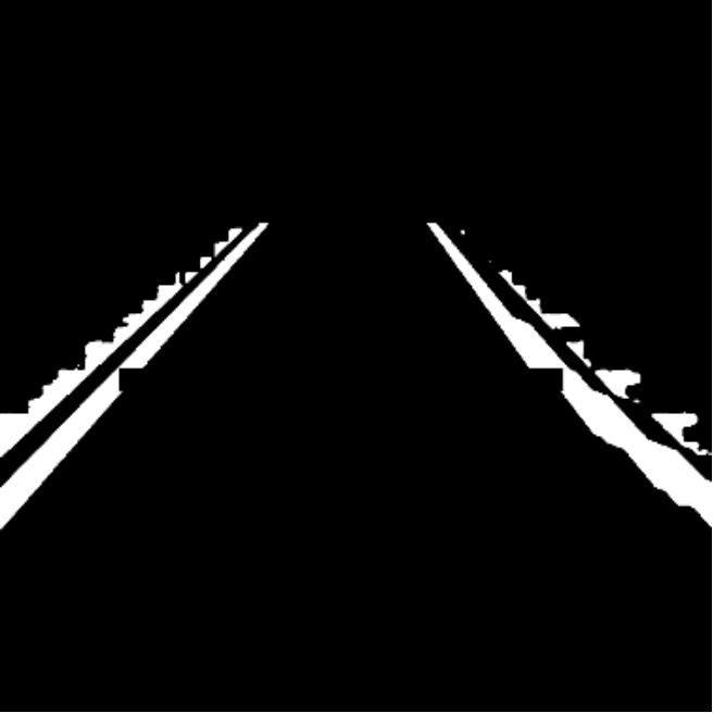
HSV Filtering: Images from the simulation camera were converted to HSV color space. This conversion made it easier to apply white color thresholds to identify potential lane areas.
Sobel Filtering: This method was used to detect the finish line. When a line perpendicular to the vehicle’s direction was identified by the Sobel filter, it was recognized as the finish line.
Noise Reduction: A median noise filter was applied to reduce pixel-level noise in the images.


Front Arduino Sketch
This sketch appears to control the front part of the autonomous vehicle, focusing on steering, acceleration, and braking. Key components include:
ROS Integration:
- The script uses ROS (Robot Operating System) for communication. It subscribes to topics and uses messages to interact with other parts of the vehicle system.
Steering Control:
- Steering commands are received as angles and converted to steps for a stepper motor.
- The steering function reads the current steering angle and adjusts the motor to reach the desired angle.
Acceleration Control:
- The acceleration function gradually adjusts the motor speed to match the desired speed.
Brake Control:
- Brake commands are received to activate or deactivate braking.
- When braking is activated, acceleration and steering are halted.
Start Command:
- There’s a start command check to initialize the movement of the vehicle.
Rear Arduino
This sketch seems to control the rear part of the autonomous vehicle, focusing on yaw measurement and wheel encoder readings. Key components include:
ROS Integration:
- Similar to the front, it uses ROS for communication, publishing data on specific topics.
Yaw Calculation:
- An MPU9250 sensor is used to measure the yaw (rotation around the vertical axis).
Wheel Encoder:
- Hall effect sensors are used to measure the wheel rotation, which can be used to calculate the vehicle’s speed or distance traveled.
- The encoder function updates the encoder count on every sensor change, indicating wheel movement.
Brake Light Control:
- The sketch controls a brake light, turning it on or off based on the brake command received.
In summary, the front arduino sketch manages the vehicle’s steering, acceleration, and braking, while the rear arduino sketch deals with orientation (yaw) and wheel rotation measurement. Both sketches interact with a central system through ROS, indicating a modular and networked approach to vehicle control.
